
Rendering

Rendering
Double Buffering is a common methode. Imagine you are drawing a sprite pixel per pixel on to the screen. Since you are doing this pixel per pixel, the image formation will be recognizeable. The solution to this is "Double Buffering".
A buffer in this case equals, according to you screen resolution, a memory block on your graphics card. For example: screen resolution = 1024*768; the size of the buffer has to be = 1024*768*3 bytes (3 because 1 byte for red, 1 byte for green, 1 byte for blue).
In "Double Buffer" mode, there exist two buffers of that size. One is called back buffer, the other is called front buffer. The front buffer is the one that is visible on the screen. The backbuffer is not visible! To do rendering in "Double Buffer" mode you have to do the following steps:
After step three you start again with step one. The main engine interface holds the function definitions. To give you a quick overview what this means, here is a short example.
void draw()
{
	sce::clearBackBuffer(sce::Colorf(0,0,0));		// clear the backbuffer with color black

	// do some rendering here, can be 2d or 3d ...		// the rendering is done by default into the backbuffer

	sce::swapBuffers();					// make the backbuffer the visible one
								// (and turn the frontbuffer into the backbuffer)
}
In its simplest form, a material is a single texture (a normal image). But a material can also be a collection of several textures, one texture drawn over the other. (In photoshop this would equal the layers concept). For each texture pass a set of parameters can be set. For example: is the texture scrolling or rotating, how are the pixels of this texture pass combined with the pixels already on the screen, ... .
The following examples show you how to achieve some standard material effects. The sce-editor is just a gui that helps creating material scripts, once you understand the concept it will be easy to use the editor too. A material is defined in a script file with extension *.mat. *.mat files can be found in directories: "data/image/", "data/entity/" and "data/world/". These files can be opened with a normal ascii editor (like: notepad).
material: floor
{
 ambient 0.588200 0.588200 0.588200
 specular 0.900000 0.900000 0.900000
 diffuse 0.588200 0.588200 0.588200
 shininess 0.100000
 transparency 1.000000
 zwrite true
 {
  map \data\world\test\textures\concrete.jpg
 }
}
Every material definition starts with the keyword "material:". This indicates the engine that a block will follow
holding information about a material. After the keyword "material:" the name of the material is defined. This
must be a unique name. The name is used for loading and identifying the material.
The paramteres "ambient", "specular", "diffuse" and "shininess" are needed when dynamic lighting is used. You can use
the sce-editor to experiment and find out yourself. "transparency" is pretty much selfexplaining, and "zwrite" is
a boolean value (can be set to "true" or "false").
Then a block follows, that defines a texture pass. After the keyword "map" a relative path follows, defining the
image data.
material: engine/cursor
{
 ambient 0.200000 0.200000 0.200000
 specular 0.000000 0.000000 0.000000
 diffuse 0.800000 0.800000 0.800000
 shininess 0.000000
 transparency 1.000000
 zwrite true
 {
  map \data\image\common\cursor.tga
  blendFunc SRC_ALPHA ONE_MINUS_SRC_ALPHA
 }
}
The new parameter "blendFunc" is added now holding two values: the source blending factor (here: SRC_ALPHA) and
the destination blending factor (here: ONE_MINUS_SRC_ALPHA). (Do not get confused about the SCR in the destination
blending factor.) If you want to understand how this works, search the internet for the topic: BLENDING.
The image data is stored in a *.tga file. The reason for this is, because *.jpg can not store alpha channels. Normally
you have three channels, a red, a green and a blue channel. Using photoshop you can add a fourth channel, an alpha
channel. The alpha channel is the mask for this image. Everything that is defined full white is completely visible,
the complete dark parts of the alpha channel mask the image pixels out.
RGB channels:
 Alpha channel:
 After blending:

material: data\image\explosion
{
 ambient 0.200000 0.200000 0.200000
 specular 0.000000 0.000000 0.000000
 diffuse 0.800000 0.800000 0.800000
 shininess 0.000000
 transparency 1.000000
 zwrite false
 {
  frame \data\image\particles\canon\explosion1.tga
  frame \data\image\particles\canon\explosion2.tga
  frame \data\image\particles\canon\explosion3.tga
  frame \data\image\particles\canon\explosion4.tga
  frame \data\image\particles\canon\explosion5.tga
  frame \data\image\particles\canon\explosion6.tga
  frame \data\image\particles\canon\explosion7.tga
  frame \data\image\particles\canon\explosion8.tga
  changeFrameAfter 0.100000
  blendFunc ONE ONE
 }
}
The block starts with the keyword "frame". You can think of this like a movie, and you define every frame
(do not confuse it with the math frame, which is a 4*4 matrix!). The parameter "changeFrameAfter" defines how long a
frame should be displayed till the next one is displayed. If the last frame is displayed the material starts with
the first one.
The "blendFunc" has now changed. The values "ONE" and "ONE" guarantee that the pixel values of the explosion bitmaps
are just added to the pixel data that is currently on screen. Recognize also the "zwrite" parameter which is set to
"false" now. This guarantees that this material is drawn after the non transparent parts in the scene.
The eight frames are displayed here:


The final material looks like this:

material: two_tex_passes
{
 ambient 0.200000 0.200000 0.200000
 specular 0.000000 0.000000 0.000000
 diffuse 0.800000 0.800000 0.800000
 shininess 0.000000
 transparency 1.000000
 zwrite true
 {
  map \data\image\console\consoleBackGround.bmp
 }
 {
  map \data\image\particles\rockettrail\proto_zzztblu3.jpg
  blendFunc ONE ONE
 }
}
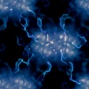
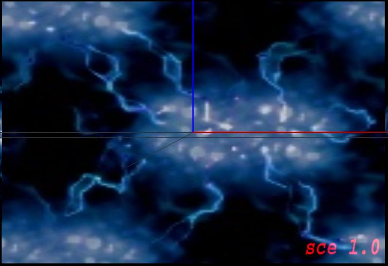
The first pass holds the image "consoleBackGround.bmp" which is rendered first. The second pass adds an effect to the
base image using image "proto_zzztblu3.jpg". See the use of the "blendingFunc"!
Base pic:
 Effect pic:
 Material with 2 tex passes:
The Virtual Screen is important when it comes to 2d. It does not effect 3d stuff. The idea behind this is,
no matter what screen resolution you use, no matter if you are in windowed or fullscreen mode, you use a 640*480
screen to render the 2d objects on the screen.
The lower left corner has the coordinates 0,0. The upper right corner has the coordinates 640,480.
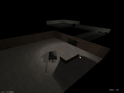 Have a look at the picture on the right. You can see 2 rooms, an alley, a tank and a spaceship.
These terms are used by the sce-editor, the database and the main engine interface. The world and sector concept is not very special.
Using the sce-editor you will see that you can create a new world and give it a name. This name is used ingame for loading the world. Further there is functionality to add multiple sectors to the new world. Give the sectors names, define geometry and collision data. For a given sector you can set multiple static lights and use the lightmaps to precalculate the light information into the textures.
The entities are a little bit more complex. An entity is everything that is moveable in the 3d world. An entity can
be defined by a graphcis model, a collision model and a physics model. Using the sce-editor you can see that the
graphics, collision and physics models are handled differently.
The graphics model can be loaded from an exported 3dmax file. The graphics model can also hold simple animation, which
can be played using the editor.
The collision model can consist of more than one primitive. A primitive can be a sphere, a triangle mesh, a box or
even a line. It depends on the form of the entity. You can combine different collision primitives to fit the entity.
The rule is, the more complex the collision model, the more expensive are the collision tests. Spheres are easy to
handle and fast, also boxes are pretty fast to check for collisions. Triangle meshes are expensive!
The physics model will be added later...
Lighting is only relevant when using the 3d graphcis part of the engine. Most realtime graphics applications use
more than one technique to lighten a 3d scene. So does the sce-engine.
A 3d scene is built up of static and dynamic objects. The static objects define the level. Basically all objects
that are not moveable, and will not change position or orientation (for example: walls, hills, trees, ...). The
dynamic objects are all the entities that can be interacted with, that are able to move (for example: players,
vehicles, ...).
The dynamic objects are lit using vertex lighting ("Gourard Shading"). This is supported by the graphics card, is pretty fast, but has its disadvanteges when the objects consist of big triangles. The big plus is, that the lighting of the object is done in realtime and changes with the light or object position changes. Additionally a dynamic object can cast a dynamic shadow. To achieve this, a flag has to be set in the entity config file or using the sce-editor.
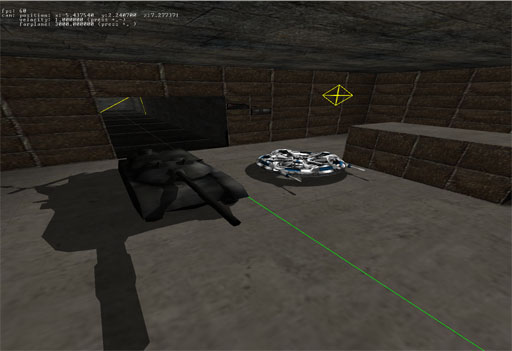
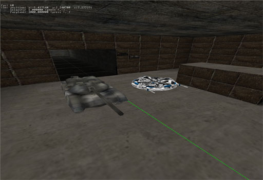 The two pictures on the right show the same scene.
In the first, the entities (tank and spaceship) are not lit. There are no highlights or darker areas on their
surfaces. Also the shadows are missing. The viewer of these pictures can get the impression that both are flying.
In the second, the objects are lit and cast shadows. Realize the yellow octagon, which symbolizes a point light.
The primary technique, lighting a static scene is using lightmaps. A lightmap is a texture that holds the light info.
This texture is combined with the regular object texture. The drawback of this technique is, that it is fixed and
can not be changed at runtime. The big plus is, the lightinfo does not have to be calculated at runtime, the data is
calculated before application start.
The lightmaps are generated using the sce-editor. In the sce-editor the geometry is imported into the scene, the
lights are placed and defined and after that the lightmaps are calculated.
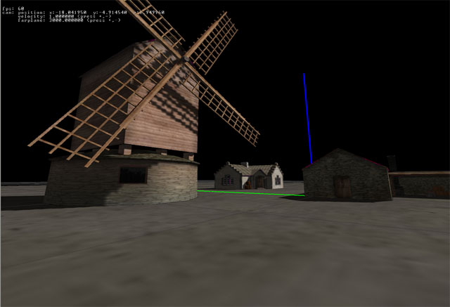
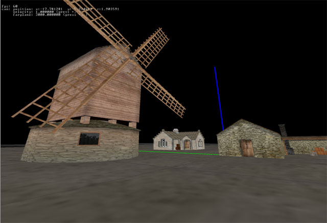 The screenshots on the right show a typical static 3d scene. There are no dynamic objects in this scene.
The first picture shows the scene without lightmaps, the second has lightmaps. The lightmaps produce the lighter and
darker areas on the surfaces and it also produces shadows.
To achieve the results you want, you should first experiment with simple geometry and one or two lights. Use a simple room and simple dynamic objects in the scene to see how all the different light parameters impact the lighting. Lighting is very important to get the right atmosphere, you should investigate into this. Lighting can improve the visual appereance of your 3d scenes enormously.